Variable Frequency Drives A Variable Frequency Drive is a motor control device that protects and controls the speed of AC induction motors. The contactor is used for starting and stopping the motor where the green and red buttons are connected.
Three Phase Dol Starter Control Overload Indicator And Power Wiring Di Electrical Circuit Diagram Electrical Jobs Electrical Wiring Diagram
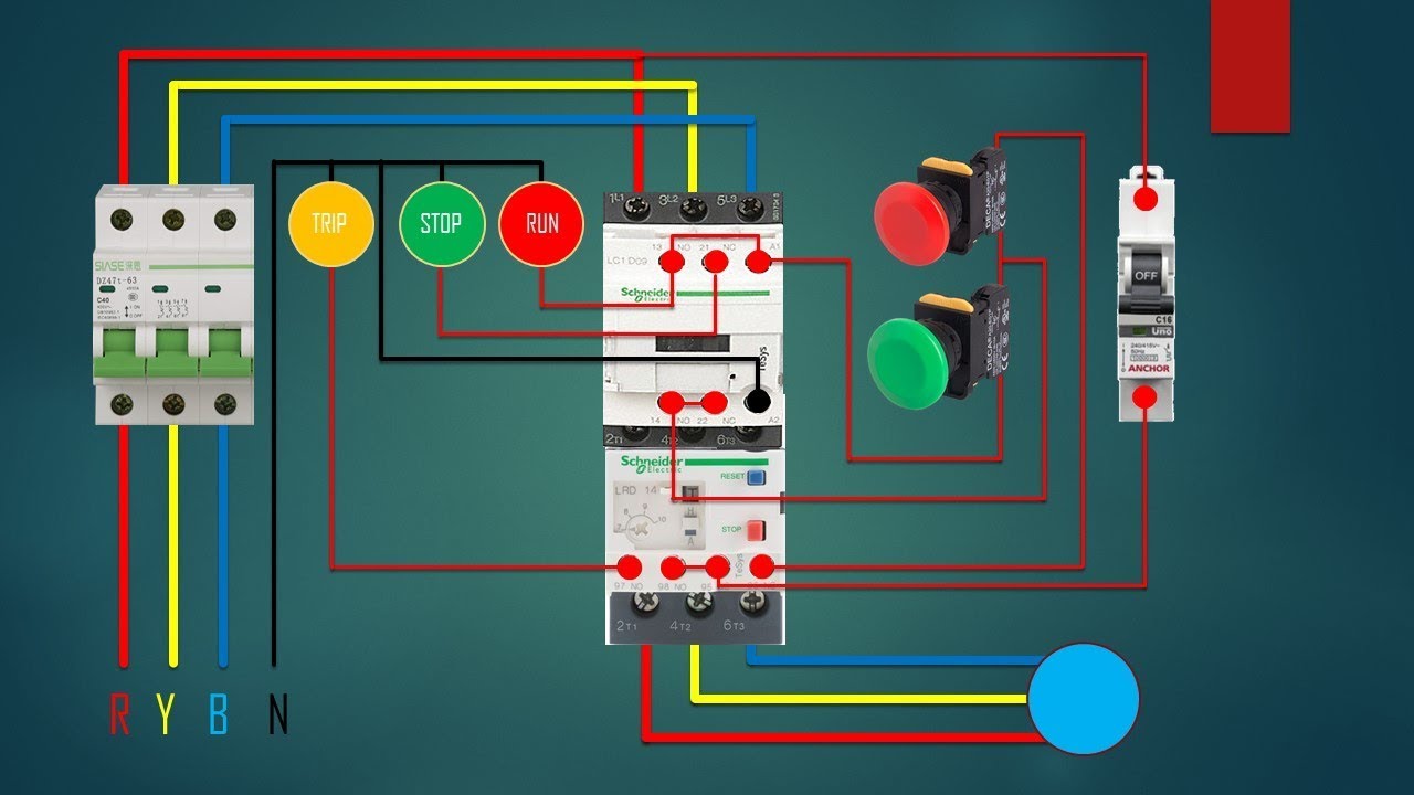
Direct On Line Starter - Wiring Diagram.

. Normally it gets one phase constant from incoming supply Voltage A1when Coil gets second Phase relay coil energizes and Magnet of Contactor produce electromagnetic field and due to this Plunger of Contactor will move and. The motor is started DOL as against a VFD starter. Motor starting and control method should be on the PIDs.
The difference being BHP is the calculated requirements needed to keep the process at maximum process capacity. HP is the size of a standard 460V. Working principle of DOL Starter.
From the VFD basics theory we know a VFD can control the speed of the motor during the start and stop cycle as well as throughout the running cycle by outputting adjustable frequencyIt also refers to as Variable Speed Drives VSD. HP Horse Power. The size could be in BHP or HP Either way we handle the data and move on.
The DOL starter is made of a circuit breaker or MCCB or fuse an overload relay and contactor or coil. The main heart of DOL starter is Relay Coil. BHP Break Horse Power.
Wiring Diagram of DOL Starter. The electric motor is the core component of an electrical drive that converts electrical energy directed by power processor into. The circuit breaker is used for protection against short circuits while the overload relay protects the motor from overloading.
In the above block diagram of an electric drive system electric motor power processor power electronic converter controller sensors eg PID Controller and the actual load or apparatus are shown as the major components included in the drive.
60 Beautiful Motor Starter Wiring Diagram Electrical Circuit Diagram Circuit Diagram Electrical Wiring Diagram

70 Luxury Single Phase Dol Starter Wiring Diagram Electrical Circuit Diagram Electrical Wiring Diagram Circuit Diagram

77 Unique Reversing Starter Wiring Diagram Circuit Diagram Electrical Circuit Diagram Electrical Diagram

Contactor Wiring Guide For 3 Phase Motor With Circuit Breaker Overload Relay Nc No Swi Electrical Circuit Diagram Electrical Wiring Diagram Electrical Wiring

Wiring Diagram For Motor Starter 3 Phase Controller Failure Relay Electrical Pleasing Three Electrical Wiring Home Electrical Wiring Electrical Circuit Diagram

Motor Control Animation Electrical Circuit Diagram Diagram Electrical Diagram

Direct Online Starter Dol Starter Electrical Diagram Circuit Diagram Electrical Wiring Diagram

Dol Starter Connection Single Phase Motor Connection With Magnetic C In 2021 Electrical Projects House Wiring Magnets

Dol Starter Connection With Indicator 3 Phase Direct On Line Starter Explain With Circuit Diagram Youtu Electrical Circuit Diagram Circuit Diagram Circuit

Dol Starter Electrical Circuit Diagram Circuit Diagram Electrical Diagram

3 Phase Motor Wiring Diagrams Home Electrical Wiring Diy Electrical Electrical Wiring

Single Phase Motor Contactor Wiring Diagram Elec Eng World Electrical Wiring Electricity Electrical Engineering

Motor Forward Reverse Wiring Diagram Elec Eng World Electrical Circuit Diagram Electrical Wiring Diagram Basic Electrical Wiring

Wiring Dol Starter Motor On Off Interlock Png 941 680 Teknik Listrik Listrik Teknik

Pin On Starter Wiring

Wiring Dol Starter Motor Star Delta Teknik Elektro Teknik Listrik Rangkaian Elektronik

Star Delta Starter Connection Diagram And Wiring Elektrik

What Is Motor Starter Types Of Motor Starters Electrical Technology Electrical Diagram Electrical Wiring Diagram Electrical Panel Wiring

Star Delta Starter Y D Starter Power Control Wiring Diagram Teknik Listrik Listrik Teknologi